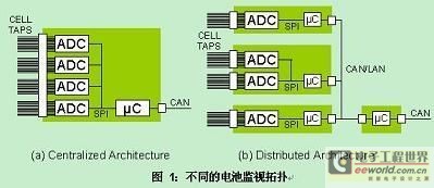
If you accept a task, for a new system monitor circuit and battery-based power supply, what strategy will you take to optimize the design of cost and manufacturability? first consideration will be the system of choice architecture as well as the location of the battery and electronic components. Basic structure clear later, then there is a problem that must be taken into account, balance coordination of circuit topology, for example, how to optimize communications and interconnection of the final product.Battery size will have a significant impact on power system structure. To using large small battery to for shape complex of battery module (or battery) did? or to using shape size is big of battery, thus due to weight problem and led to on battery number of limit or caused other of size limit? this may is design variables maximum of part, because shape novel of battery constantly listed, and people also in constantly efforts, to battery module or battery integrated to products in the Hou, will and whole products concept more consistent. For example, in automotive design cases, batteries may eventually spread some of the space in the vehicle, these spaces if you do not put the battery, efficiency is very low.Another consideration is that the battery (or modular battery), the battery management system (or a system), and finally application interface between test signals and/or telemetry signal interconnects. In most cases, you can do a shell, to integrate some data acquisition circuit in the battery or batteries, so if you need to replace, the production ID, calibration, using specifications important information with replaceable components, such as take away. This kind of information on battery management system (BMS) or maintenance equipment might be useful, and minimizing the wiring harness in the required high voltage rating is the number of wires.Next, given mechanical concept design, monitor hardware topology consists of a precisely defined, the required number of batteries support decisions. In automotive applications, typically total more than 100 battery point, and modular system will determine a given circuit system for measuring how many batteries. The most common case is that in safe disconnection "repair plug" means all cells divided into at least two groups. By voltage under fault conditions less than 200V, this method minimizes the maintenance staff may face risk of electric shock. Overall dimensions larger battery packs means that two isolated data acquisition system, each may support 50-battery connector. In some cases, all the electronic components on the printed circuit board in an affordable, but this would require a large number of interconnection, as shown in Figure 1 (a) as shown. Alternatively, the electronic components can also be housed, more closely integrated in the battery module, but this would require the use of telemetry links. In order to achieve reliable data integrity built into the automotive wiring harness remote measuring circuit must be a solid agreement, such as the extensive use of CAN bus. Though true CAN bus interfaces involve several network layer, but you can easily use PHY layer BMS LAN structure, efficient communication within the module. This type of distributed architecture in Figure 1 (b) as shown. This topology allows distributed computing workload between several smaller processors, thereby reducing the required data transfer rate and reduce LAN method likely to cause EMI problems. Eventually the BMS interface is likely to be to a primary system management processor CAN-bus wiring, and will need to be defined (or at the beginning of the requirements) specific information for transactions.
 Picture name
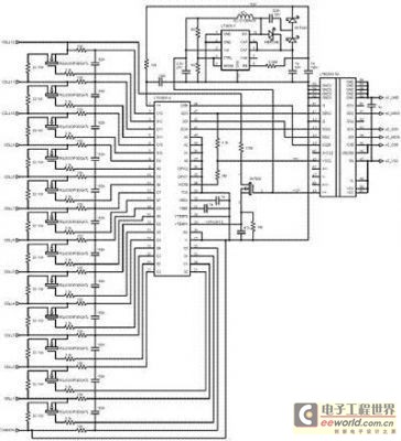
Other factors may also have an impact on physical structure and monitoring circuit. As far as the lithium-ion battery required battery capacity balance, resulting in an additional thermal management issues (removal of heat), and if you need to source a good balance, and power conversion circuits. Temperature probes are often distributed across modules to provide a method of voltage and charge status to associate, and thus need some support circuit connection. Design is an often overlooked consideration when when when idle or on store shelves before the product installation, battery is leaking should be minimal. In some cases, additional control wiring is necessary.In achieving these structures, there is a common measurement of functional components, the Widget includes a multichannel ADC, security isolation barrier and a certain amount of local processing power. Figure 2 shows an implementation of data acquisition functionality Extensible design platform. In this figure, the function is the core component of bullying lierte LTC6803 battery monitor IC, also shown are an SPI data separator and some optional special-purpose circuits. The circuit includes input filters and passive balance function, form a complete set of 12 batteries data acquisition solutions. If required, this type of circuit can simply be copied to support more cell measurement programme, while sharing the main microcontroller local SPI port, micro-controllers, in turn, provide the main external CAN-bus or other LAN data link required.
 Picture name
Compared with the previous generation monitors, LTC6803 major improvements is to support power down and/or powered by batteries alone. When the power from the v + pin removed, the battery load will fall to zero (only nA level diode leakage). Power supply can be provided by the connected battery voltage, or from a separate power supply available to V+, as long as the voltage and battery pack is always at least as high. To achieve the simplicity, LTC6803 can also get power directly from the battery, in this case, the minimum power state (standby) will consume only 12uA. LTM2883 through an internal data separator isolated DC-DC converter, powered from the main processor, the device will automatically power with the main processor. LTM2883 is a very useful function, it can to isolate electronic components (battery side) provides a large and independent machinery of power. A small power boost function components (LT3495-1 in Figure 2) is one such drive, independently to the LTC6803 power supply, so that the batteries only provide ADC measurement input current (that is, valid conversion averages < 200nA). This circuit has the absolute lowest parasitic battery leakage, while eliminating any current mismatch, this mismatch could gradually lead to the battery capacity imbalances. LTC6803 is a convenient function, there are two free, precision ADC input similar to the battery input. This handy feature allows for very little additional auxiliary measurement circuit, including temperature, calibration, signal or load current measurement. Is a particularly useful measure, using a gate resistor voltage divider measurement of the entire battery pack voltage, method as shown in Figure 2 (in 12:1, connect to the VTEMP1 input). When the circuit is power off, disconnect FET, so that the measurement of current does not unnecessarily increase the burden of the battery. Since the port filter can be customized independently of the battery input to, the accurate calculation of the charging current in order to achieve the desired, genuine 200sps Nyquist (Nyquist) sampling rate is possible. Can be used on a single cell measurement to periodically dividers provide software calibrated to the entire battery pack, so you don't need expensive resistors. Another useful use of auxiliary input is, measurement of high accuracy calibration power (such as bullying lierte LT6655-3.3, a benchmark for accuracy is 0.025%), in this usage, allow software with channel to match the natural channel, correcting all the other channels. Please note that thermistor temperature probes without battery voltage as a benchmark, they generally do not need a 12-bit resolution. Such probes usually applies to connect directly to the microcontroller, thus leaving LTC6803 auxiliary input, in order to achieve the more demanding functions. In short, in the battery management system, there are many factors to consider, in particular those factors that determine the package limit. When packaging design ideas together, and consider also has the potential to generate mechanical effect of electronic circuits and the structure of information flow (for example: number of connectors and wires) is also very important. Once these factors are weighed and packaging design ideas mature, simply insert a LTC6803 platform, a well-established, scalable and cost-effective data collection solution is done.
(Editor:SIPANI Battery/kuang)


 SIPANI Powerwall Home Battery Lifepo4 Lithium Battery 48v 200ah 51.2v 100ah Power Wall 5kwh 6kwh 7kwh 9kw 10kwh
 48v 50ah 100ah 150ah 200ah 250a 300ah Lithium Battery Cabinet Rack Mount Battery Solar Storage System Lifepo4 Battery 5kwh 10kwh
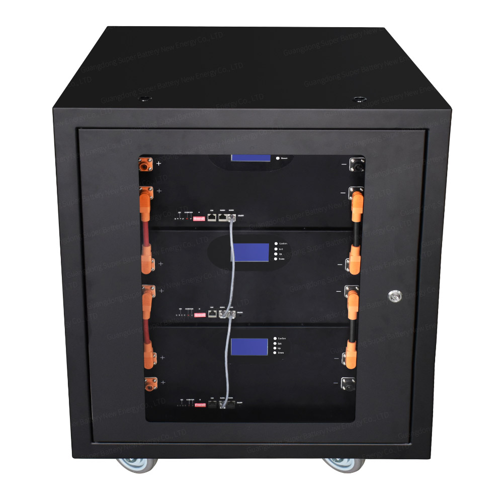 SIPANI 30kw 20kw Lithium Ion Battery Cabinet 10kwh 48v 200ah Lithium Battery Pack 300ah 400ah 500ah 600ah Solar Lifepo4 Battery
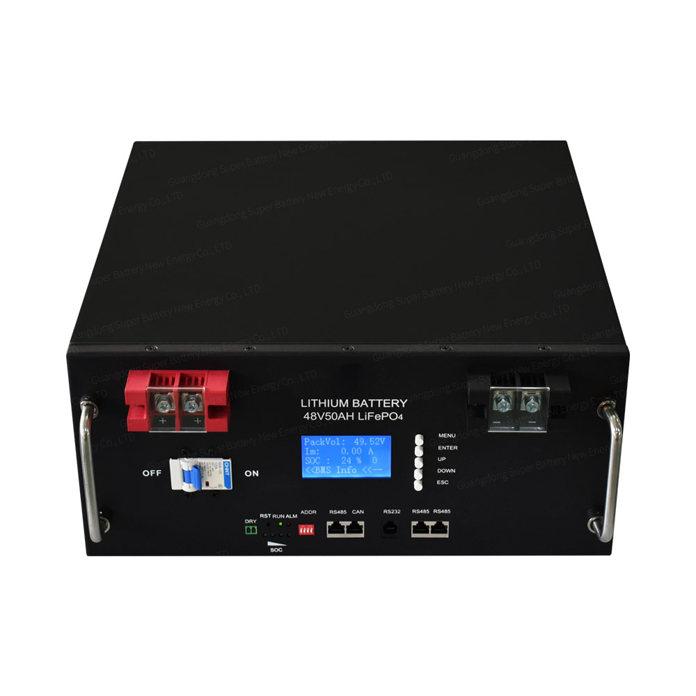 SIPANI Server Rack Lifepo4 Battery 24v 48v 50ah 100ah 200ah 2.5kwh 5kwh 10kwh Rack Mounted Lithium Ion Battery For Off-grid
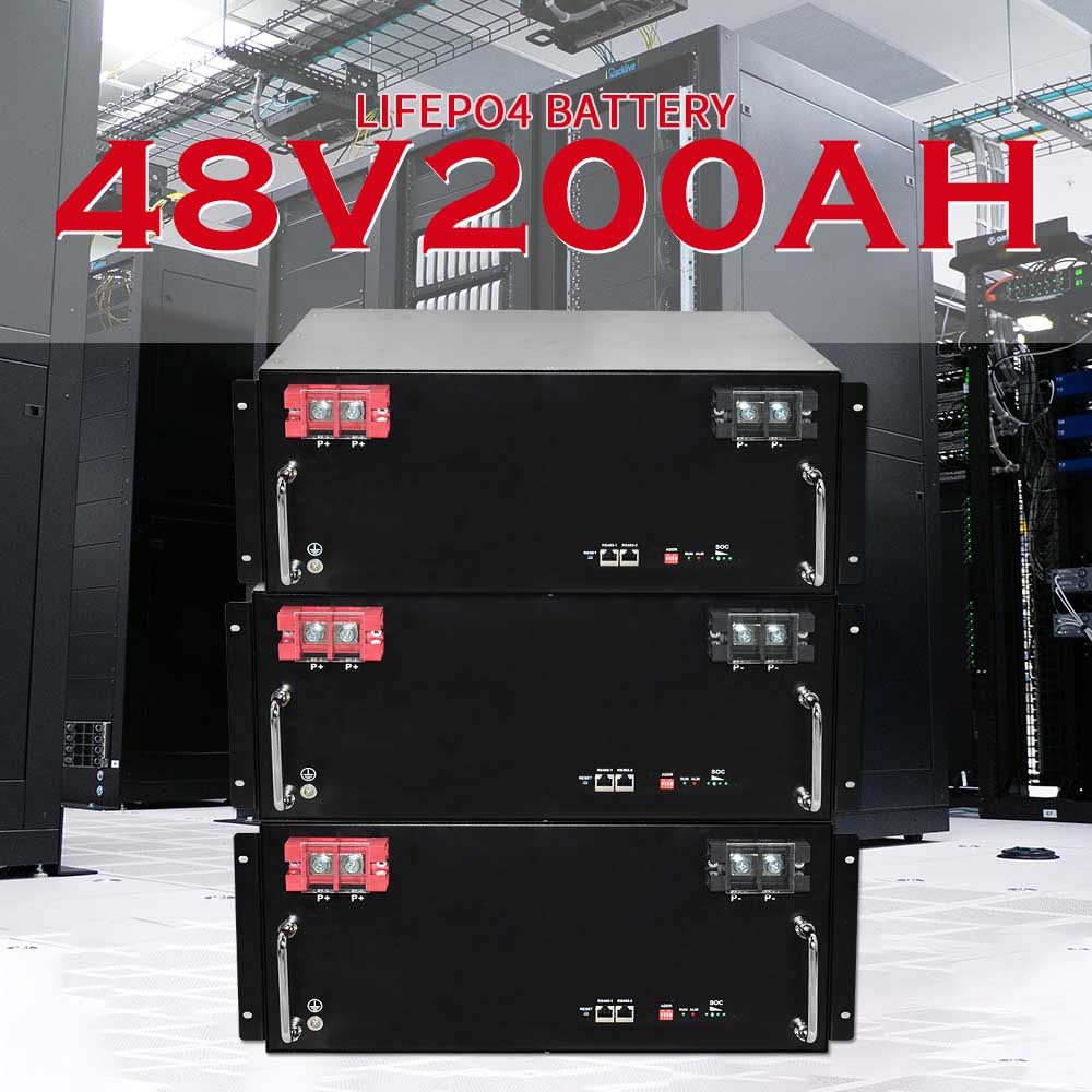 SIPANI Lithium Ion Solar Battery 10kwh 48V 150ah 200ah Server Rack Lifepo4 Battery Pack 51.2V 5kwh 7kwh 10kwh 15kwh 20kwh 30kwh
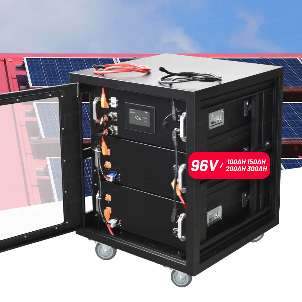 High Voltage Lifepo4 Battery 96v 200ah Lithium Battery Pack For 96v 10kw 15kw 20kw 30kw Solar Home System Electric Car